| Specification of Embedded Temperature and Humidity Transmitter LFH75 | |
| Relative Humidity | |
| Sensor | Humidity Sensitive Capacitor |
| Range | 0%~100%RH |
| Output | RS485/Modbus,0~10VDC,4~20mA,0~20mA |
| Accuracy | ±2%@ 20℃ & 20~80%RH |
| Response Time | ≤10s(20°C, slow flow air) |
| Temperature | |
| Transducer | PT1000(class A) |
| Range | 0-50°C,-20-60°C,etc. |
| Output | RS485/Modbus, 0~10VDC, 4~20mA, 0~20mA |
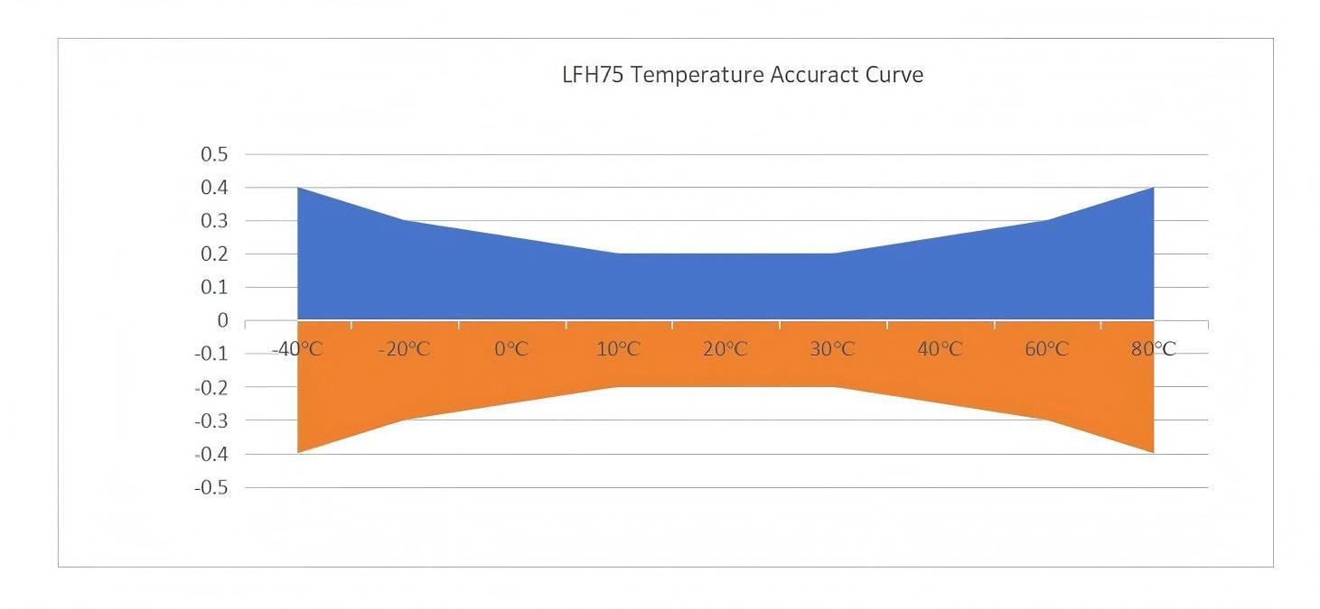
| Accuracy | ±0.2℃@ 10°C-30℃ see chart for other ranges |
Temperature Accuracy Curve

Power supply: 16-35VDC or 24VAC ±20%.
Note: An isolation transformer is required when using AC power.
Output Load: ≥10KΩ (voltage type); ≤500Ω (current type).
Display Resolution: 0.01℃, 0.01% RH.
Housing Material: Base shell PC, panel stainless steel 304, probe stainless steel 304 probe.
Operating Environment: -20 to 60℃, 5%-95% RH(non-condensing).
Storage Environment: -20 to 60℃, 5%-95% RH.
Protection Level: Front panel: lP65 after installation; Probe: lP65 (stainless steel sintered and H₂O₂ filter); lP30 (metal U-groove filter)
.jpg)
.jpg)
Note:
1. Only when the output option is V10, A0, or A4, the temperature range 1-8 must be selected,otherwise,only0 can be selected.
2. Example LFH75-A42202 represents an embedded temperature and humidity transmitter with current output 4-20mA, temperature range -20-60℃, stainless steel sintered filter, and 2-meter cable length.
3. Prolonged exposure of the sensor probe to high temperature and humidity environments may cause humidity drift, which can be restored by placing it in a normal environment.
 English
  français
  Deutsch
  Español
  italiano
  русский
  português
  العربية
  Türkçe
  Zulu
Zulu 