Most Popular
The actuator of the compressor pressure switch is a spring, whose compression force is changed by a special screw. In factory settings, the compression force of the spring is usually set to 6 to 8 atmospheres in the pneumatic network, as described in the user's manual.
The pressure switch design includes two mandatory sub-components-an unloading valve and a mechanical switch. The unloading valve is connected to the air supply line between the receiver and the compressor. It controls the operation of the motor. If the compressor drive is turned off, the unloading valve on the receiver discharges the excess compressed air to the atmosphere, thereby unloading the moving parts of the compressor from the excess force they must generate when the compressor is running. Turn it on again. This prevents the motor from being severely overloaded in terms of allowable torque. When the engine starts at no load, the valve is closed and unnecessary pressure is not applied to the actuator.
The mechanical switch has a standby function to prevent accidental starting of the engine. After pulling up the button, the driver turns on and the compressor runs in automatic mode. When the button is pressed, even if the pressure in the pressure air network is lower than the required pressure, the compressor motor will not start.
In order to increase the safety of work, the industrial structure of the compressor pressure switch is also equipped with a safety valve. It is useful, for example, in the case of sudden engine stops, piston breaks, or other abnormal conditions.
Optionally, a thermal relay may be installed in the pressure switch housing to monitor current in the primary circuit. If this parameter increases for any reason, the thermal relay will turn off the motor to avoid overheating and subsequent winding damage.
How to connect and configure the pressure switch?
The pressure switch is located between the unloading valve and the secondary motor control circuit. Normally, pressure switches are equipped with four threaded heads. One is used to connect the device to the receiver and the second is used to connect the control pressure gauge. One of the other connectors can be used to install the relief valve and the remaining connectors can be used with a conventional ¼ inch threaded plug. The existence of a free connector allows you to install control gauges in a user-friendly location.
The pressure switch is connected in the following order:
1. Connect the device to the receiver discharge valve.
2. A control gauge is installed (the thread inlet is silenced if not required).
They are connected to terminals of the motor control circuit. In the case of network voltage fluctuations, not directly connected, but through the power supply filter connection. This is also necessary when the power of the contact design exceeds the load current of the motor.
Adjust the relay to the desired compressed air pressure value using adjusting screws if necessary.
You can check that the power supply voltage matches the factory setting of the compressor pressure switch. For example, in a three-phase network with a voltage of 380V, the switch must be a three-pin set, and for 220V, a two-pin set.
Adjustments are made when the receiver is at least two-thirds full. To perform this operation, the switch is disconnected from the main power supply, and after removing the top cover, the adjusting screw is responsible for adjusting the pressure value. On the plate next to it, the generally accepted pressure symbol (P-pressure) is usually marked with the direction of rotation of the screw, which decreases or increases with it.
Connect the pressure switch to the compressor and set it.
One of the main indicators of air compressor is working pressure. In other words, the level of air compression generated in the receiver must be kept within a certain range. It is not convenient to perform this operation manually with reference to manometer readings, so the compressor automation unit works to maintain the desired compression level in the receiver.
The device and working principle of the automation unit:
To keep the pressure in the receiver at a certain level, most air compressors have an automatic device, a pressure switch.
The device opens and closes the engine in time to prevent compression levels in the tank from being too high or too low.
The compressor pressure switch is a block containing the following elements.
Terminal. Designed to connect cables to relays.
Spring. Install with adjusting screws. The pressure level in the receiver depends on their compression strength.
Membrane. It is mounted under the spring and compressed under the action of compressed air.
Power button. Designed to start and force stop devices.
Connect flange. They can be anywhere from one to three. Flanges are used to connect compressor switching relays to receivers and to connect relief valves with pressure gauges to them.
In addition, it can also supplement the automatic device of the compressor.
Unloading valve. Designed to relieve pressure after an engine is forced to stop, making it easier to restart.
Thermal relay. The sensor prevents the motor windings from overheating by limiting the current.
Time relay. Mounted on a compressor with a three-phase motor. The relay disconnects the starting capacitor a few seconds after starting the engine.
Safety valve. If the relay action fails and the compression level in the receiver rises to a critical value, the relief valve will operate to release air to prevent an accident.
Gear reducer. A manometer is mounted on the element to measure air pressure. The unloader allows you to set the level of compression required for air entering the hose.
The pressure switch works as follows. After starting the compressor engine, the pressure in the receiver begins to rise. As the pressure regulator is connected to the receiver, compressed air from it enters the membrane unit of the switch. The membrane bends upward under the action of air and compresses the spring. The spring is compressed, the switch is activated, the contacts are opened, and the engine of the device stops. As the compression level in the receiver decreases, the diaphragm mounted in the pressure regulator bends downward. At the same time, the spring is released, the switch closes the contact, and the engine starts.
Wiring diagram of pressure switch to compressor
The connection of the relay controlling the air compression ratio can be divided into two parts: the electrical connection between the relay and the unit and the connection between the relay and the compressor through the connection flange. Depending on the motor installed in the compressor, 220 V or 380 V, there are different pressure switch connection schemes. I've been guided by these diagrams, but with some electrical engineering knowledge, you can connect the relay yourself.
Connect the relay to the 380 V network
To connect the automation to a compressor operating over a 380 V network, a magnetic starter is used. The following is a diagram of connecting automation to the three phases.
Connect the pressure switch to the device
Connecting the pressure switch to the compressor is very simple.
Screw the pressure switch to the receiver branch using its central threaded hole. For better thread sealing, it is recommended to use smoke proof tape or liquid sealant. In addition, relays can be connected to the receiver via a reducer.
A pressure gauge or safety relief valve may be connected to the remaining relay outputs. The latter is successfully installed. If a pressure gauge is not required, the free outlet of the pressure switch must be plugged with a metal plug.
In addition, wires from the power source and the engine are connected to the sensor contacts.
After the pressure switch is fully connected, it needs to be configured for proper operation.
Compressor pressure control
As mentioned above, after a certain degree of air compression is generated in the receiver, the pressure switch turns off the engine of the device. Conversely, when the pressure drops to the opening limit, the relay starts the engine again.
By default, relays for single-phase equipment and units operating on 380 V networks already have factory Settings. The difference between the lower limit and upper limit for starting the engine should not exceed 2 bar. Users are not recommended to change this value.
But there are often situations that force you to change the factory Settings of the pressure switch and adjust the pressure in the compressor yourself. The lower opening threshold can only be changed because the relief valve will vent air after changing the closing upper limit to an increase.
Compressor pressure control is as follows.
Turn on the equipment and record the gauge reading as the engine is turned on and off.
Be sure to disconnect the device from the power supply and remove the cover from the pressure switch.
After removing the cover, you will see bolts with springs. Bolts are usually represented by the letter "P" with the symbols "-" and "+" and are responsible for generating the upper pressure. When this pressure is reached, the device will shut down. To increase the air compression level, turn the regulator to the "+" sign, then lower it-to the "-" sign. First, it is recommended to rotate the screw half a turn in the desired direction, then turn on the compressor and use a pressure gauge to check the degree of pressure increase or decrease. Record at which indicators of the equipment the engine will be shut down.
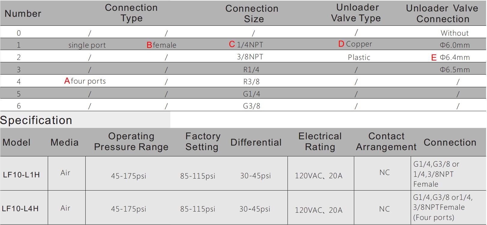
The LF10-L pressure switch is a pressure-operated electric switch for use in regulating the tank pressure between two preset values on electrically driven air compressors. It is available with an unloader valve,which prevents compressors from starting under load,and an On-Off button for manual cut off the compressor. A four port manifold style is available.


 English
  français
  Deutsch
  Español
  italiano
  русский
  português
  العربية
  Türkçe
  Zulu
Zulu 

