Most Popular
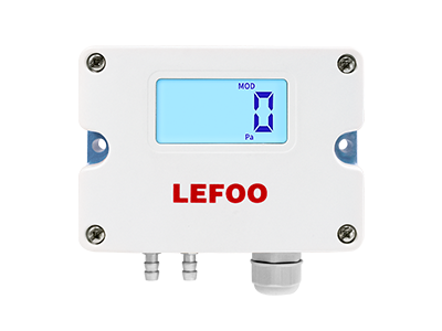
The key raw materials, components and parts of the differential pressure transmitter are imported. The whole machine has been strictly assembled and tested. The product has the characteristics of advanced design principle, complete varieties and specifications, simple installation and use and so on.
Due to the use of ASIC amplifier design, the packaging of differential pressure transmitter is reduced, and the capsule structure and flange are miniaturized. The weight of this model is reduced to half of the original model. ASIC design not only reduces the number of parts, but also improves the reliability of the amplifier.
So how to install correctly is very important for each of our staff. Today Lefoo pressure transmitter manufacturers will tell you how to reduce the error when installing the micro differential pressure transmitter. I hope it can help you.
(1). When measuring liquid steam, the impulse pipe shall be connected upward to the process pipe of the process, and its slope shall not be less than 1/12.
(2). In case of gas measurement, the impulse pipe shall be connected downward to the process pipe of the process, and its slope shall not be less than 1/12.
(3). High points shall be avoided during the layout of liquid impulse piping and low points shall be avoided during the layout of gas impulse piping.
(4). The two impulse pipes shall maintain the same temperature, and shall be as short and as large as possible.
(5). There shall be no gas in the impulse pipe filled with liquid. When isolation liquid is used, the liquid level of impulse pipes on both sides shall be the same.
(1). When measuring liquid pressure, the installation position of micro differential pressure transmitter shall avoid liquid impact (it is water hammer phenomenon) to avoid overpressure damage of the sensor.
(2). In case of freezing in winter, anti-freezing measures must be taken for the differential pressure transmitter installed outdoors, and the instrument insulation box shall be protected by adding a conducting band. When not in use, drain the water in time to prevent the liquid in the pressure tap from expanding due to icing and causing damage to the sensor.
(3). When wiring, pass the cable through the waterproof joint (accessory) or winding pipe and tighten the sealing nut to prevent rainwater from leaking into the transmitter housing through the cable.
(4). When measuring the liquid pressure, the pressure tap shall be opened at the side of the process pipeline to avoid sedimentation and slag deposition.
(5). The flange liquid transmitter shall be prevented from contacting with corrosive or overheated media, and the dregs shall be prevented from depositing in the conduit.
(6). When the single flange liquid level transmitter measures the gas pressure, the pressure tap shall be opened at the top of the process pipe, and the flange liquid level transmitter shall also be installed at the upper part of the process pipe, so as to quickly inject the deposited liquid into the process pipe.
(7). For differential pressure transmitter, pay attention that the impulse pipe of the sensor shall be installed at the place with small temperature fluctuation.
(8). When measuring steam or other high-temperature media, a condenser such as buffer pipe (coil) shall be connected (more than one meter is recommended), and the working temperature of the transmitter shall not exceed the limit.
The above instructions are precautions for use under normal and general working conditions. Different site conditions shall be adjusted according to specific working conditions
More Related Products


 English
  français
  Deutsch
  Español
  italiano
  русский
  português
  العربية
  Türkçe
  Zulu
Zulu 